Finally the design process is here. After a gruelling round of drawings, analysis and ‘debates’ we present before you the design process which we will be adopting in our endeavour towards the accomplishment of our AMPHIBIOUS VEHICLE.
NOTE: we have used some technical terms (hull,etc.) in this article which may cause some interpretation problems for non-technicians. This is intentional as we want the reader to search out these terms and experience the joy of learning through self discovery.
1. Engine Transmission: The engine to be incorporated in our vehicle is a Honda Street 100 engine. It is a 4 stroke engine with single cylinder and specifications as 97.2 cc, 6 bhp and a maximum rotational speed of 7500 rpm. The engine is fitted with an automatic centrifugal clutch with four forward speed. This engine will be used to provide a rear axle drive with the help of a chain and sprocket mechanism.
2. Steering System: Considering the vehicle weight, size, shape and driving conditions, we came up with the plan of using a steering which includes a Pitman arm with two tie rod ends. This mechanism will be a 100% Ackerman mechanism with an Ackerman angle of 24 degrees. If we consider a turning radius of 3 metres, then the rod ends travel is of 5 inches.
3. Braking System: We will be using Disc Brakes in our vehicle. We had a choice to make between Disc brakes and Rim brakes. Though Rim brakes are cheap, light, mechanically simple, easy to maintain, and powerful, they perform poorly when the rims are wet. Rim brakes require regular maintenance. Brake pads can wear down quickly, and have to be replaced. Over longer time and use, rims become worn. Rim brakes also heat the rim because the brake functions by converting kinetic energy into thermal energy. It is not a problem in light-weight vehicles but in case of a heavy-weight vehicle and tandems in mountainous regions, the heat build-up over a long descent can increase tire pressure so much that the tire blows off the rim causing serious accidents. For this reason, disc brakes are often fitted instead of rim brakes in this situation.
4. Wheel Specifications: The engine will provide the vehicle a top speed of about 80 km/hr. As the estimated kerb weight of the vehicles is 300 kg, the wheels we came up with have a wheel base of 55.5 inches and a wheel track of 50 inches. The tyre dimensions are 26 x 1.3/8 inches.
5. Material to be used for fabrication: We have decided upon to use 1018 steel pipes to use as our material for the chassis. The outer diameter of the pipes is 1 inch with a thickness of 0.07 inch. With such specifications, the total weight of the chassis is coming out to be 8.41 kg (only the tubular frame). The yield strength of this material is close to 386 MPa and the elastic modulus is in the range of 190-210 GPa. The reason we chose this material is that it is readily available and easily weld-able with arc welding.
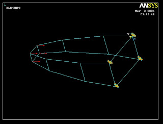
6. FE Analysis of the chassis: In order to get an unbreakable frame, a proper analysis was done on ANSYS for different designs of the frame considering different loads. A frontal impact of 5-G force and a side impact of 3-G force were considered. After analysis, the points of maximum stress were checked suitable numbers of cross bars were added in the design to minimise the stress. With the above specified yield strength and elastic modulus of the material, a factor of safety of about 1.8 was achieved. As you might remember, the snapshots of the ANSYS analysis was posted a couple of days back and you can easily watch them simply scrolling down your mouse button.
7. Hull design: the role of the hull is important when the vehicle is in water. Considering the total weight of the vehicle, it was found that the depth of the vehicle inside water is 0.5 metres. So, the minimum volume of water to be displaced by hull came out to be 0.3cu.metres. Taking into account the factor of safety, the hull has been designed by taking this volume as 0.6cu.metres.
8. Propeller Design: the point where the axle containing the propeller system will be fixed to the chassis, can be decided after knowing the water level as the ideal position will be the centre of the propeller coinciding with the water level. Depending on the availability of propellers as well as the type that suits our need, we plan to devise the propeller system in the most satisfying manner for the vehicle.
Thus, this is the basic framework of our design and also the road map of our process. We will be glad to answer any quarry regarding our design from anyone and at the same time, will be enlightened to incorporate suggestions and corrections into our design in pursuit of perfection.
While posting comments, you can choose to be Anonymous (to avoid the trouble of signing up) and in the dialogue box, type your name and contact (if you wish) after your comment.
Cheers!!!


